Sbooster’s White Paper
Electro Static Discharge (ESD) of a SMPS can kill your audio device
Some of you will have noticed that we have added with our Vbus Isolator and Ultra upgrade for the Uptone Audio Regen a warning paper (appendix I) for ESD of a switch-mode power supply (SMPS) when swapping a USB-cable. ESD can damage the USB-circuit of both your streaming device or connected playback device. In this white paper we are going to show you the following:
How to identify if you are in the risk category for ESD;
Basic technical background information;
Technical explanation of the issue;
USB-cable swap in a virtual simulation of SMPS ESD;
Easy way to prevent the risk of damage.
How to identify if you are in the risk category.
You are in the ESD-risk category, if your streamer/NAS/CAS/Etc., Active USB tweak or DAC/SPDIF/I2S convertor is powered by a SMPS, see picture I
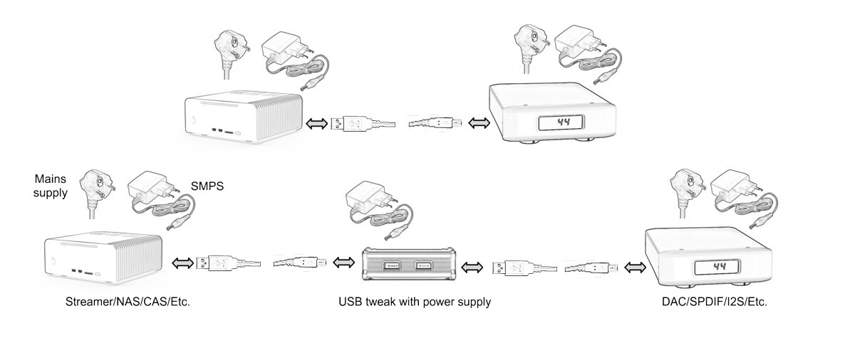
Picture I
Basic technical background information
Earth/Ground
To understand the technical explanation, it is important to understand the usage of the words “Earth” and “ground”. Earth is related to the AC mains and is most of the times called ground. In electronic circuits, when the negative (-) sides of the components are connected to a shared plane, this is also called ground. So ground can refer to the AC mains Earth or to the negative side of an electronic circuit. To make it more complex, most manufacturers connect the AC mains Earth to the electronic ground inside an audio device. Most external linear power supplies have these ground/Earth connection as well.
Simplified SMPS circuit
Next we are going to show you the basic electronic circuit of a SMPS, see picture II

Picture II
The 90-264V AC mains is rectified and charges the first bulk (storage) capacitor. The voltage of this capacitor can be as high as 350V DC. The energy of the bulk capacitor flows x times per second thru the primary side/windings of the transformer. On the secondary side/windings of the transformer the lower voltage energy is stored in the second bulk capacitor. The last step is the voltage regulation stage which gives the SMPS a stable output voltage.
NB: SMPS technology uses a transformer between the (AC) input and (DC) output of the PSU. This means that the output of a SMPS is galvanic isolated from the mains.
In the red rectangles you find a capacitor that is connected between the input and output of the SMPS. Manufacturers install these capacitors for two reasons. The first reason is to meet the EMI regulations and second is that the capacitors are lowering the output noise of a SMPS significantly.
Technical explanation of the issue
The risk of the ESD is caused by the capacitors in the red rectangles, see picture II. The voltage potential of the capacitors can be measured with a oscilloscope. For this measurement we connect the ground of the oscilloscope to the AC mains Earth pin. The SMPS is connected to the AC mains and we leave the DC output unconnected. This is called floating. Although the DC output of the SMPS is rated at 12V DC the scope measures a peak voltage of +/- 144V AC (286Vpp). In the next picture you will find an overview of the test setup. To open the oscilloscope measurement, please click picture III.

Picture III
Next we are going to perform the same test on a USB connected audio system with a SMPS powered streamer and a high-end DAC with a built-in power supply. Like most high-end equipment, this DAC has the AC mains Earth connected to the electronical ground. The USB cable is connected to the DAC side only, so the USB cable is floating. As you will see on the scope we get the same test result as we did with the previous test.

Picture IV
The extreme high voltage of these capacitors become a risk when the floating USB cable is connected to the SMPS powered streamer. At the moment that the pins of the USB connector make contact with the pins of the USB port of the streamer the capacitors can rapidly discharge to Earth. This because the electronic ground of the DAC is internally connected to the mains Earth.
USB-cable swap in a virtual simulation of SMPS ESD
To make the ESD risk more clear and to show you what is happening when the USB connection is made we have made an electrical equivalent circuit of the audio system above. In the next picture you will find the electronic circuit and explanation.

Picture V
The USB connector is represented by a switch. To ‘connect’ the USB cable you simply press the switch with your mouse. To start the SMPS ESD risk simulation, please click following picture.

We have also made the electrical equivalent circuit where both audio devices are powered by linear power supply solutions. To start the LPSU ESD no-risk simulation, please click following picture.

Easy way to prevent the risk of damage
We hope that with this technical explanation of ESD caused by SMPS that you have a clear view on the risks you run when swapping a USB cable. As you probably will have noticed in the simulation “smps- can-kill…………..”, the current is not always at the same level and sometimes the current flow does not appear at all. In real life you can swap your USB cable 100 times without facing any issue’s and at swap 101 one of your devices is damaged.
To prevent this issue, simply disconnect the SMPS from the mains before you swap a cable. Or replace all SMPS by one of our audio grade external power supplies.
Last but not least, also swapping a RCA, XLR or ie. SPDIF cable can lead to the same damage, be warned.
*** END ***
Appendix I

ESD Warning Paper